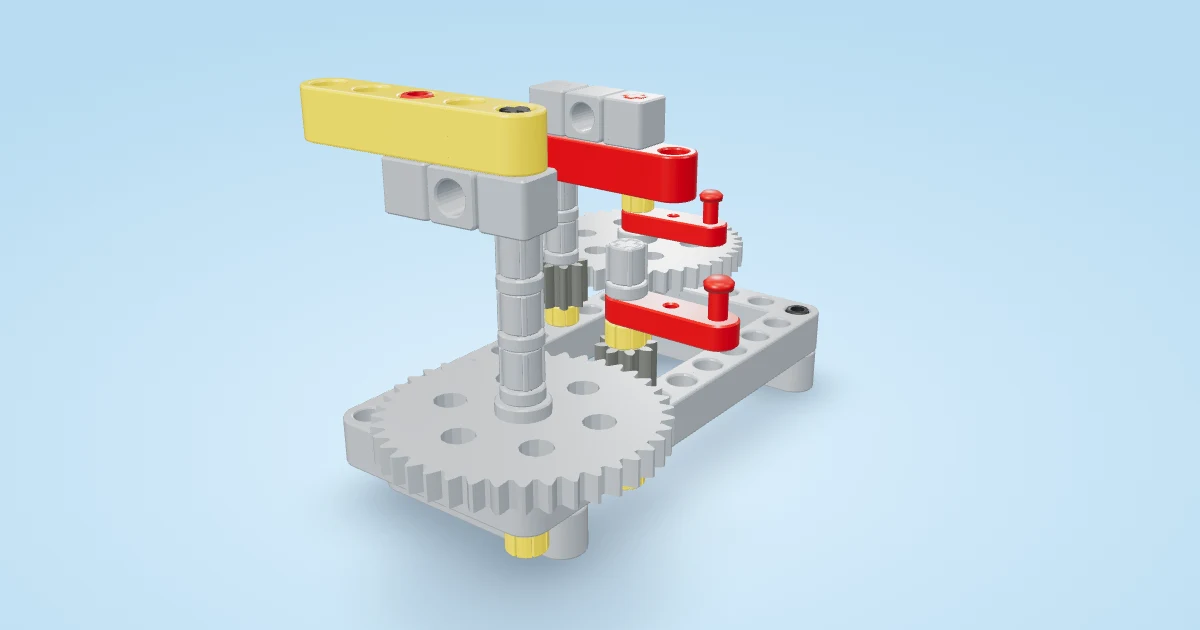
Two gear reductions multiply because the second stage receives motion that the first stage has already slowed. In our new Compound Counting Bench, an 8-tooth gear drives a 40-tooth gear, then another 8-tooth gear on that same middle axle drives a second 40-tooth gear. Five input turns make one middle turn; five middle turns make one output turn. That means 25 input turns for one output turn, with the output following the input direction.
A small bench for a very large idea
Brick Experiment Channel’s credited demonstration combines many gear stages to illustrate an enormous reduction. Its description supplies the stage-product formula and gear inventory; the video shows the mechanism growing, rather than giving a complete hole-by-hole assembly guide. The huge result is a mathematical rotation prediction, not evidence that the final shaft has completed a turn. We use the repeat-a-stage idea to make a short, inspectable original educational model. Our frame, shaft layout, retention and instructions are our own; they do not reproduce the creator’s machine.
Open the free Compound Counting Bench instructions. This level 2 hand-operated model takes about 20 minutes and uses two 8-tooth gears, two 40-tooth gears, a 5×11 frame, cross axles and retaining bushes. It has two separate gear planes, one above the other. Follow the animated assembly before trying the counting challenge, and use the free booklet when you want instructions beside the physical bench.
Follow the shared middle axle
The lower input gear passes eight teeth per turn. The first large gear needs forty teeth for its own complete turn, so it turns one fifth as far in the opposite direction. This is the ordinary external gear ratio relationship. The large middle gear and small upper middle gear share one cross axle. They turn together, even though they have different diameters and tooth counts.
Now follow the upper mesh. One middle turn passes eight teeth from its small gear. The upper output gear again needs forty teeth for a complete turn, so it travels one fifth as far as the middle shaft. Multiply the speed fractions: one fifth times one fifth is one twenty-fifth. Both external meshes reverse direction, so the final output returns to the input direction. The compound gears explanation shows why a shared shaft is the important connection.
Predict before you turn
Try the counting lab below. Start with both driven gears set to 40 teeth. Enter your prediction for the input turns needed to make one output turn, then check it. Move the input slider to five turns and inspect the middle and output readouts. Next move it to 25 turns. Negative turns let you repeat the reasoning in reverse.
Interactive: Compound counting challenge. Predict and compare two shared-shaft reduction stages. Two 8-tooth drivers and 40-tooth driven gears require 25 input turns for one forward output turn; five input turns produce one reverse middle turn. Change one stage, check your prediction and reset the ideal counting model.
Change only the first driven gear to 24 teeth in the ideal lab. Its reduction becomes three instead of five, while the second stage remains five. Predict the new total before checking. These alternative sizes are mathematical comparisons, not approved substitutions in the physical bench: different tooth counts need different centre spacing. Return to the original 40-tooth settings before following the build’s instructions.
Why this is different from an idler
Compare the Speed-Cancelling Gear Bridge. Its single middle gear receives motion on one side and passes the same tooth count onward on the other, so that middle tooth count cancels from the final ratio. Our new bench has two different gears on the middle shaft. The lower 40 teeth receive motion; the upper eight teeth transmit it. Their tooth counts cannot cancel as though they were one gear.
The Gear Speed Lab is another useful comparison. It gives you separate fast and slow pairs. This bench connects two reductions in sequence, making it possible to count the already reduced middle motion feeding a second reduction. Adding five plus five would describe neither the tooth flow nor the observed turn counts.
Run a fair counting experiment
Put removable marks on the red input, blue middle and yellow output bushes. Choose a fixed starting reference and turn the red input slowly 25 complete turns. Tally in five groups of five, recording the middle shaft at each checkpoint. Repeat three trials with the same parts, direction and starting reference. Then reverse the input and record a separate reverse trial. Stop if gears bind; keep fingers away from meshing teeth.
| Input turns | Predicted middle turns | Predicted output turns | Your observed counts |
|---|---|---|---|
| 5 | −1 | +0.2 | Record both shafts |
| 10 | −2 | +0.4 | Record both shafts |
| 25 | −5 | +1 | Repeat three trials |
These table values are ideal predictions, not measurements. A start-up delay after changing direction can reflect tooth clearance, often called backlash. Take up that slack gently before choosing your counting reference. If a shaft slides, a gear rubs the frame or a bush squeezes the stack, repair the assembly before drawing conclusions about the ratio. Check the two mesh heights and retained axles rather than moving supports by eye.
A slow output is not unlimited strength
Real stages introduce friction, clearance and flex. A reduction trades speed for ideal turning effort, but it does not create energy or prove a particular load capacity. This bench has no tested lifting attachment, measured efficiency or rated torque. Its animation models the intended turn counts; it does not certify physical performance. The useful outcome is an explanation you can test with your own parts: two separate meshes, a shared middle shaft, multiplied reductions and a complete counting record.
Interactive: Check yourself. A few quick questions on the ideas in this guide, each with an explanation.
- Two 8-tooth drivers each turn a 40-tooth driven gear. How many input turns make one output turn?
- The middle 40T and 8T gears share a keyed cross axle. What stays equal?
- Does a 25:1 reduction prove the bench can lift 25 times more weight?