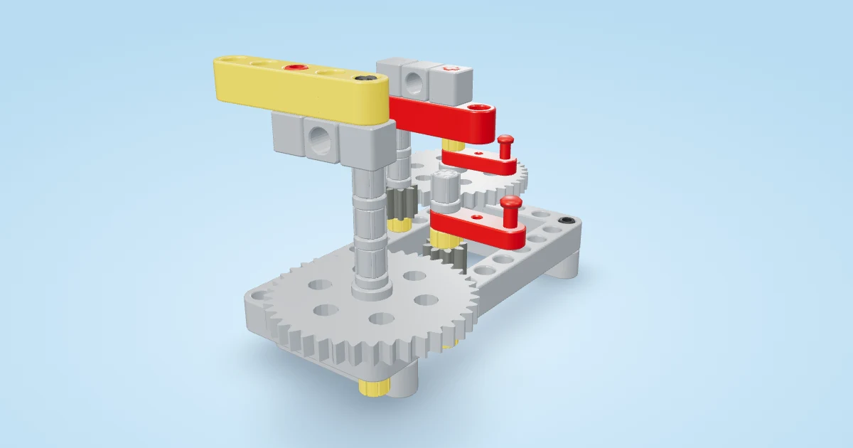
A single-start worm needs twenty-four turns to rotate a 24-tooth wheel once in the ideal meshing model. That slow output is only half the lesson. The worm also produces thrust along its shaft, so a fixed-position counting mechanism needs actual axial stops. Without those restraints, an appealing movie may show a shaft that can slide out of its intended mesh.
One demonstration, a different purpose
S. L. Froden’s credited video demonstrates a worm drive and linkage in which the worm can deliberately slide axially. That sliding is part of the demonstrated reciprocating mechanism. Our new Worm Counting Bench deliberately teaches the contrasting fixed-shaft arrangement. It is an original unloaded hand-operated bench, not a recreation of the creator’s layout or a claim that their purposeful slider was a mistake.
The free guide provides compatible-parts inventory, animated assembly and a printable booklet. This corrected page replaces the earlier aluminium fabrication lesson at this address. The bench uses ordinary beams, axles, bushes, a worm and a 24T gear; its goal is to make the reduction and thrust restraints visible before attaching an output load.
Follow the assembly sequence
Start with the flat frame, split support blocks and four stationary feet. The feet support the tabletop model; the rotating input shaft must not become its table support. Fit the input shaft and two stationary upright posts with their prescribed lower stops and spacers.
Construct the output module separately: shaft, 24T wheel, inner retaining bushes and one bare tower. Lower that group into the frame before adding the worm, upper input bearing and crank. Insert the tower mounting pins only after the module is seated, then build the opposite bearing around its free shaft. This order matters because a complete pinned tower cannot be pushed through an obstructed insertion path just because the final position looks plausible.
Now fit the worm, upper beam and opposed shaft retainers. The input shaft has two separated bearing locations and stops on the appropriate sides of those bearings. The output has two towers and outside end stops. The retained posts transfer the upper bearing’s loads back to the base. Turn slowly by hand and stop if a bush presses the shaft against a support so tightly that it cannot rotate freely.
Count the slow output
Open the gear-ratio lesson. A single-start worm carries one continuous thread around its shaft. One input revolution advances the meshing wheel by one tooth. Twenty-four teeth therefore give an ideal 24:1 reduction. Four input turns predict one-sixth of an output turn, or 60°. Twelve predict 180°; twenty-four predict 360°.
The movie prescribes an input speed of 24 revolutions per minute and an output magnitude of one revolution per minute. Its full sixty-second loop includes one complete output revolution. Those are animation inputs and calculated kinematics, not speeds measured with a physical motor. The axes are perpendicular; the signed direction follows the authored worm orientation and cannot be guessed from a parallel spur-gear rule.
Put removable marks on the input crank and output bush. Starting after gently taking up slack in one direction, count four input turns and record the output angle. Repeat three times. Do the same for twelve turns, then for twenty-four. Keep parts, starting alignment, direction and measuring method unchanged. Reverse separately and record any delay before the output follows.
| Input turns | Ideal output angle | Your observations |
|---|---|---|
| 4 | 60° | Record after assembly |
| 12 | 180° | Record after assembly |
| 24 | 360° | Record after assembly |
These values assume ideal tooth engagement. Report your reading uncertainty and whether the trend follows the prediction. Do not invent observations from the animation. An unloaded counting test does not establish torque capacity, wear or transmission efficiency.
Investigate the locking claim carefully
A worm is sometimes described as impossible to drive backwards. Whether a real assembly resists backdriving depends on thread lead, friction, lubrication, load and compliance. Reduction alone does not certify a brake. The interactive challenge below lets you compare a simplified friction assumption across the displayed drive types and lead angles and explain a predicted tendency.
Interactive: Worm lock tester. Crank a load up with spur gears, a single-start worm or a two-start worm, predict whether it stays up when you let go, then release the handle. Change the friction to see when a worm holds and when it slips, and play five scored challenges.
Change one control at a time, state your prediction and reset before trying another combination. Its model is educational, not a measurement of these construction parts. Do not turn its readout into a promise that this bench can hold a lifted object. Leave lifting loads out of the experiment and avoid forcing the output shaft backwards.
Diagnose slipping or binding
If the worm moves up or down, compare the opposed bushes with the assembly steps: a bearing guides rotation, but it does not automatically stop axial sliding. If the output tilts, inspect both tower mounts and outside stops. If teeth rub or the crank catches the output wheel, stop rather than adding motor power. This original bench places the crank above the output’s swept envelope; an earlier crane layout was rejected as a baseline because its actual animated meshes collided.
Compare a parallel gear pair in Gear Friends and a different reduction in the Speed Bench. Explain which design makes its load path easiest to see. Our digital assembly and full-range mesh checks support this authored bench, including a regression for an incompatible worm pitch. They remain a procedural-geometry review, not a physical prototype or a manufacturing tolerance certificate.
Interactive: Check yourself. A few quick questions on the ideas in this guide, each with an explanation.
- A single-start worm advances a 24T gear by how much per input turn?
- What resists the axial force on this bench’s worm shaft?
- Does a low-friction slider in the lab certify a physical lifting brake?