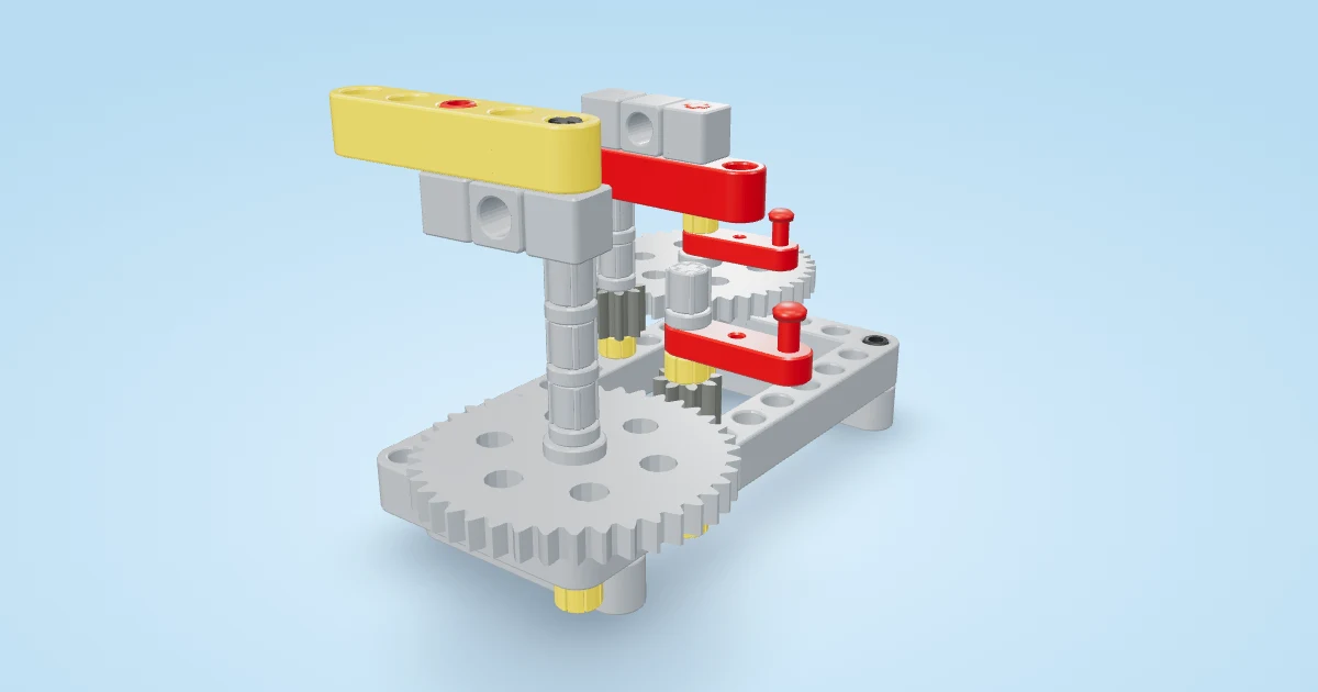
A symmetric differential allows two output shafts to turn at different speeds while their average equals the carrier speed. In the ideal model, left speed plus right speed equals twice carrier speed. If one output stays still and the carrier turns at six revolutions per minute, the other output turns at twelve. That relationship explains motion; it does not say which wheel has grip or measure delivered torque.
Make the carrier the input
2in1 Bricking’s credited custom differential demonstration explains the principle using a creator-built housing and bevel gears. Its job in this lesson is to show the relationship between carrier rotation and two outputs. Our new Differential Hand Bench uses a standard assembled 62821 differential component in an original tabletop support frame. We do not copy the creator’s custom housing or claim our instructions assemble their exact model.
This corrected article replaces the earlier reversible custom-fabrication lesson at this URL. Open the free compatible-parts guide for the actual inventory, animated steps and printable booklet. The inventory counts the bare 62821 housing and three separate 6589 single-bevel 12T gears. Assemble those loose gears using the explicit symbolic preassembly step and the linked official reference; 32270 double-bevel gears are not substitutes. A bare housing with missing internal gearing is not a working differential, even if a digital exterior looks complete.
The input is the housing itself, gently turned by hand. There is no external driver gear meshing with its ring. That choice makes the average-speed relationship visible without an additional ratio or steering mechanism obscuring the outputs.
Support the shafts before operating
Build the frame and split blocks first, including the stationary feet that give it a stable tabletop footprint. First seat the transverse gear on the housing’s internal post, then fit the two inward-facing side gears. Insert each of the two separate four-module half shafts into its own side gear, following the preassembly step and official reference. The two shafts reach their own side gears; they are not one continuous axle joining the outputs through the centre.
Fit the bushes at the housing necks and inner bearing faces, then a bare tower around one end. Lower the module into position before inserting its mounting pins. Build the other tower around the free output and fit the outer retaining bushes. This sequence provides an unobstructed assembly path rather than asking a complete pinned support to pass through the finished model.
The separated towers guide shaft direction. Bushes outside the towers retain the shaft ends, while neck and inner-face bushes establish the housing’s intended position. The housing is allowed to rotate; translation and tilting are restrained by real neighbouring parts. Check the coloured ends and every stop against the instructions. Holding a loose output in the correct place is not an acceptable substitute for a missing bearing or retainer.
Compare three cases
First rotate the carrier slowly with both outputs free. They may turn approximately together when their resistance is similar, but the differential does not guarantee an equal split of speed under arbitrary friction. Mark both outputs so you can compare their turns.
Next lightly restrain one output while turning the housing. The other should turn farther for the same carrier turn. Release it before forcing a jammed shaft. Finally hold the carrier stationary and rotate one output gently: the other output should turn oppositely. These three cases explore the same relationship with different constraints, rather than three unrelated rules.
| Constraint | Ideal relationship | Your recorded observation |
|---|---|---|
| Similar freely turning outputs | Both may approach carrier speed | Record after testing |
| Left held still | Right = twice carrier speed | Record after testing |
| Carrier held still | Right = negative left | Record after testing |
Use the same starting marks, direction and slow hand-turning method for three trials of each case. Record any sticking, unequal resistance or reading uncertainty. These entries are predictions, not completed physical results. The animated bench shows the held-output case with prescribed carrier speed 6 rpm, left zero and right 12 rpm; it does not measure those speeds in a physical prototype.
Predict a turning comparison
The differential explanation connects this average-speed law to a vehicle turning a corner. An outside wheel follows a longer path than an inside wheel, so their speeds differ when they roll without slipping. Use the lab to predict the direction of the change before moving a control.
Interactive: Differential cornering simulator. Drive a car around a corner and compare inner and outer wheel speeds, then try a slippery wheel with the differential open and locked.
The corner lab is an ideal geometric comparison with its own displayed dimensions and assumptions. It is not a simulation of this tabletop bench’s internal bevel-gear contact, tyre grip or measured torque. Reset it and compare a wide turn with a tighter turn, then explain why the average can remain fixed while the difference grows. That explanation is more useful than memorizing one pair of numbers.
Interpret the model honestly
The viewer simplifies the standard differential’s housing and internal gear visuals. Its decorative tooth shapes are not a CAD tolerance certificate, and the movie’s ideal average-speed rule is not an observed simulation of all internal tooth contacts. Our bench never uses the decorative ring as an externally driven mesh. Digital checks instead review assembly, full carrier rotation, clearance and unwanted shaft/housing motions against the authored surrounding geometry.
If one side will not turn, inspect the assembled internal gears and ensure its axle reaches the correct side gear. If both outputs act as one shaft, check that they are truly separate half shafts. If the housing drifts sideways, check the neck bushes and bearing-face stops; stop before continuing. Do not fix a missing internal gear by squeezing the housing harder.
Compare the directly coupled shafts in Gear Friends and the reduction in the Speed Bench. A differential adds freedom for unequal output speeds; it does not create traction by itself. This unloaded original bench has no measured load rating, efficiency result or road-handling claim. Treat physical observations as new evidence to record, not numbers to borrow from its animation.
Interactive: Check yourself. A few quick questions on the ideas in this guide, each with an explanation.
- In the ideal symmetric differential, which relationship holds?
- Carrier speed is 6 rpm and the left output is held. What is the ideal right speed?
- What keeps the half shafts supported while the housing turns?