🕰️ Spring Escapement Clock: step-by-step build
A ticking pin-wheel clock powered by the pull-back motor's spring. Tick… tock… tick…
Inside the pull-back motor hides a coiled spring. Wind it up and let go, and it spins everything in a flash. A clock needs that energy to come out a little at a time. The trick is the escapement. Our escape wheel is a big gear with two pins sticking out of it, and the pendulum carries a frame with two pins of its own, the pallets. A wheel pin always rests against one pallet. On every swing one pallet lifts out of the way and the other drops in, so the wheel can only jump a quarter turn before it is caught again: tick… tock. As each pin slips past a pallet it nudges the pendulum, which helps keep it swinging. Pendulum clocks have worked like this for more than 350 years!
- Level 4 of 5 (tricky)
- About 50 minutes
- 22 steps, 68 parts
- Powered by: Pull-back
- Series: Mechanical Wonders
What you will learn
- Escapement: Lets a clock move one tooth per swing.
- Pendulum: A swinging weight keeps steady time.
- Stored Energy: Energy can be saved up in a spring and let out later.
- Gear Ratio: Fast or Slow: A big gear turning a small gear makes it spin faster.
Build these first
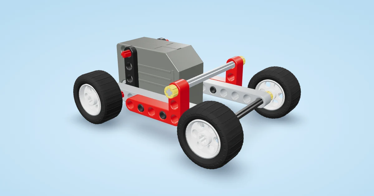 🏁 Pull-back Racer: Pull it back, let it go — ZOOM! A racer with a spring for an engine. (level 2 of 5, about 12 minutes, 10 steps)
- 🌬️ Bevel-Gear Windmill: Turn the handwheel at the bottom — the sails spin at the top! (level 3 of 5, about 25 minutes, 16 steps)
Parts you need
- 1 × Open frame 5×11
- 18 × Black pin (grippy)
- 4 × Beam 15
- 8 × Blue long pin
- 4 × Split pin block
- 4 × Red axle-pin
- 1 × Beam 7
- 1 × Pull-back motor
- 5 × Beam 5
- 1 × Axle 9
- 10 × Half bush
- 1 × Axle 6
- 1 × Medium gear (24 teeth)
- 1 × Tiny gear (8 teeth)
- 1 × Giant gear (40 teeth)
- 1 × Open frame 5×7
- 1 × Beam 11
- 1 × Thin beam 4
- 1 × Axle 4
- 1 × Yellow-hub wheel
- 1 × Axle 11
- 1 × Hand crank
Steps
- Lay the white 5×11 frame flat, long side across. This is the clock's stand.
- Push black pins down into the frame's four corner holes so they stick out underneath.
- Press a 15-hole beam onto each pair of pins from below, pointing from back to front: its holes 5 and 9 (counting from the back) on the pins. These are the clock's long feet.
- Left foot: push blue long pins up into the 3rd and 5th holes of the frame's back long side and slide two split pin blocks down onto them, one on top of the other.
- Push a red axle pin into each block, pointing forwards, and stand a 15-hole post on both. Two pins — the post can't lean.
- Right foot: the same in the 7th and 9th holes — two blue long pins and two split pin blocks.
- Two red axle pins and the second 15-hole post.
- Push black pins into hole 8 of both posts, pointing backwards, and press a 7-hole mount beam onto them (its holes 1 and 5).
- Push 2 black pins into holes 4 and 6 of the mount beam and press the pull-back motor's bottom holes onto them, output hole in line with the middle of the posts.
- Escape-wheel bearings: push a blue long pin through hole 11 of each post so it sticks out on both sides. Press a 5-hole crossbar onto the front ends and another onto the back ends.
- Pendulum bearings: the same at the top holes (hole 15) of both posts.
- Spring-shaft bearing: push black pins into hole 9 of both posts from the front and press a 5-hole crossbar onto them.
- Hold a half bush against the front of the motor and push a 9-long axle from the front through the middle of the lowest crossbar, the half bush and the motor. Then hold a half bush in the gap between the two lower crossbars and push a 6-long axle from the front through the front crossbar, the half bush and the back crossbar, until its end is level with the back of the back crossbar.
- Slide the 24-tooth gear onto the motor axle, up against the crossbar, and a half bush in front of it.
- Slide the tiny 8-tooth gear (meshing with the 24) and a half bush onto the upper axle.
- Escape wheel: push black pins into two opposite round holes of the yellow 40-tooth gear, from the front, and slide it onto the upper axle with the pins pointing at you. A half bush on the axle tip holds it on.
- Pallet frame: push black pins into holes 2 and 4 of the top row of a 5×7 frame, from the back, so they stick out of the back: they are the pallets.
- Push black pins into the middle holes of the frame's top and bottom rows, from the front, and press the 11-hole rod onto them so its 4th and 10th holes (counting from the top) sit on the pins.
- Push black pins into holes 2 and 3 of a thin 4-hole beam and press it onto the front of the rod's top end, holes lined up.
- Push a 4-long axle through the bottom hole of the rod with a half bush behind it, and put the yellow-hub wheel on the front: the pendulum bob.
- Pivot: push an 11-long axle from the front through a half bush, the thin beam's top hole and the rod's top hole, its front end level with the bush. Slide a half bush onto it right behind the rod, and another one 4 holes further back, so 4 holes of axle stick out behind it.
- Hang the pendulum: push the pivot axle's back end through both top crossbars until the last half bush on it touches the front crossbar. The pallets now sit beside the escape wheel's pins. Lock the axle with a half bush behind the back crossbar, and put the red crank on the back of the motor axle.
Play time
Wind the crank a few clicks, then give the pendulum a small push: tick, tock, tick, tock! Count the tick-tocks while the crank goes once round (you should get 6). Now move the bob two or three holes up the rod (the hole just above it holds the frame's pin) — does the clock tick faster or slower?
Real-world inspiration
Pin-wheel escapement — https://en.wikipedia.org/wiki/Escapement#Pin_wheel_escapement ; Instructables "Lego Clock Escapement" — https://www.instructables.com/Lego-Clock-Escapement/ ; HTBI LEGO pendulum clock — https://htbi-moc.com/blogs/news/building-time-a-working-lego-pendulum-clock