📐 Quarter-Phase Crank Bench: step-by-step build
One shaft turns two equal-radius markers, a quarter turn apart.
Two equal-radius markers share one shaft but reach the same viewing-axis extreme at different input angles. This original two-level bench fixes the upper arm a quarter turn ahead of the lower one. It isolates crank phase from angular speed, inspired by Brick Technology’s multi-cylinder air-engine demonstration. It is not a pneumatic engine, piston assembly or firing-order model.
- Level 2 of 5 (easy)
- About 20 minutes
- 13 steps, 31 parts
- Powered by: Hand-crank
- Series: Starter Builds
What you will learn
- Crank & Slider: A turning crank pushes a rod back and forth.
- Axles: An axle is a cross-shaped rod — anything on it turns together.
- Frames: A frame is a ready-made strong rectangle.
- Pins: Grippy or Smooth: Pins join beams together — some hold tight, some let things swing.
- Bushes & Spacers: Bushes stop things sliding off an axle.
Build these first
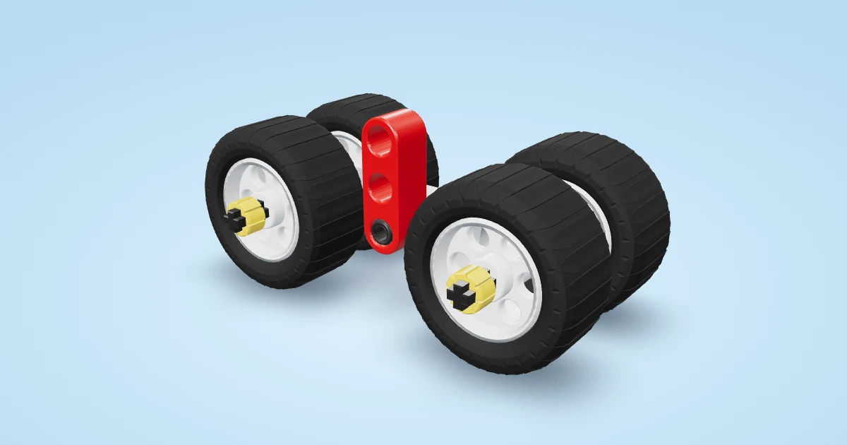 🚗 Tiny Roller: Your very first rolling car — only 13 pieces! (level 1 of 5, about 5 minutes, 6 steps)
Parts you need
- 1 × Open frame 5×11
- 4 × Axle 3
- 8 × Bush
- 8 × Black pin (grippy)
- 3 × Beam 5
- 1 × Axle 8
- 4 × Half bush
- 2 × Medium gear (24 teeth)
Steps
- Lay the 5×11 frame flat. Its four corner holes will hold the feet; the middle holes on its long sides will hold a bridge.
- Fit a 3-module axle through this corner. Hold it while fitting a full bush underneath as a foot and another full bush above as a retainer. Repeat at all four corners; the feet must rest level.
- Fit a 3-module axle through this corner. Hold it while fitting a full bush underneath as a foot and another full bush above as a retainer. Repeat at all four corners; the feet must rest level.
- Fit a 3-module axle through this corner. Hold it while fitting a full bush underneath as a foot and another full bush above as a retainer. Repeat at all four corners; the feet must rest level.
- Fit a 3-module axle through this corner. Hold it while fitting a full bush underneath as a foot and another full bush above as a retainer. Repeat at all four corners; the feet must rest level.
- Push two black friction pins upward through the middle holes of the long sides. Press the end holes of a flat 5-hole beam onto them, across the open centre. Two separated pins keep this bearing bridge rigid.
- Fit a vertical 8-module axle through the bridge’s centre round hole. Hold it while fitting a half bush directly underneath and another directly above. Leave the shaft free to turn, with minimal axial play.
- Slide a 24-tooth gear down onto the upper spacer. Its cross hole keys it to the shaft. It is a mounting hub here, not a meshing gear.
- Place two black pins upward in opposite gear holes, one hole spacing either side of the axle. Fit a flat 5-hole beam by its second and fourth holes. Two separated pins lock the crank arm to the hub. Add a half bush above the arm on the shaft.
- Fit a black friction pin pointing upward in the arm’s outer end hole. Its centre is two hole spacings from the shaft: a 16 mm crank radius. The opposite end stays empty.
- Slide a second 24-tooth mounting hub onto the lower arm’s top half bush. This separates the two arm levels. Its cross hole keys it to the same shaft; neither gear meshes with another gear.
- Fit two friction pins upward in the upper hub’s opposite holes along the long direction of the frame. Fit a flat five-hole beam by its second and fourth holes, pointing along that long direction. Add a half bush directly above the arm to retain this upper assembly. The two arms are perpendicular when viewed from above.
- Fit the upper marker pin pointing upward at the end toward the first holes of the frame: its centre is at frame position two across and three along. From above, the lower marker points across the frame and this marker points toward its short end. Both are two hole spacings from the shaft, at separate heights. Keep their full circles clear.
Play time
Hold the stationary frame on a level table and gently turn the exposed shaft. View the marker centres from directly above. Both complete one circle per shaft turn and maintain a quarter-turn separation. On separate paper, note when each reaches its rightmost coordinate; keep paper, hands and rulers out of the sweep. This is not a piston, valve or pneumatic engine. Stop for loose retainers, a moving bridge or rubbing arms. We have not physically tested the model.
Credited demonstrations and component sources
- Running Lego Engines with Air — Brick Technology: Multi-cylinder crank timing inspires the question; our two-marker phase bench uses unmodified construction parts and does not recreate the air engine.