📐 Crank Orbit Bench: step-by-step build
Trace a crank pin’s circle and compare its one-axis travel at equal angle steps.
A crank pin follows a circle, not a straight line. This original measurement bench has a rigid two-pin crank arm on a retained vertical shaft. Turn it gently and compare the outer pin’s positions at equal angle steps. Inspired by redshoebox’s oscillating-mechanism demonstrations; it is not their machine or a piston assembly.
- Level 2 of 5 (easy)
- About 15 minutes
- 10 steps, 25 parts
- Powered by: Hand-crank
- Series: Starter Builds
What you will learn
- Crank & Slider: A turning crank pushes a rod back and forth.
- Axles: An axle is a cross-shaped rod — anything on it turns together.
- Frames: A frame is a ready-made strong rectangle.
- Pins: Grippy or Smooth: Pins join beams together — some hold tight, some let things swing.
- Bushes & Spacers: Bushes stop things sliding off an axle.
Build these first
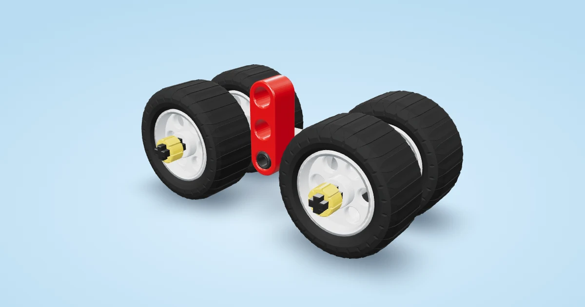 🚗 Tiny Roller: Your very first rolling car — only 13 pieces! (level 1 of 5, about 5 minutes, 6 steps)
Parts you need
- 1 × Open frame 5×11
- 4 × Axle 3
- 8 × Bush
- 5 × Black pin (grippy)
- 2 × Beam 5
- 1 × Axle 6
- 3 × Half bush
- 1 × Medium gear (24 teeth)
Steps
- Lay the 5×11 frame flat. Its four corner holes will hold the feet; the middle holes on its long sides will hold a bridge.
- Fit a 3-module axle through this corner. Hold it while fitting a full bush underneath as a foot and another full bush above as a retainer. Repeat at all four corners; the feet must rest level.
- Fit a 3-module axle through this corner. Hold it while fitting a full bush underneath as a foot and another full bush above as a retainer. Repeat at all four corners; the feet must rest level.
- Fit a 3-module axle through this corner. Hold it while fitting a full bush underneath as a foot and another full bush above as a retainer. Repeat at all four corners; the feet must rest level.
- Fit a 3-module axle through this corner. Hold it while fitting a full bush underneath as a foot and another full bush above as a retainer. Repeat at all four corners; the feet must rest level.
- Push two black friction pins upward through the middle holes of the long sides. Press the end holes of a flat 5-hole beam onto them, across the open centre. Two separated pins keep this bearing bridge rigid.
- Fit a vertical 6-module axle through the bridge’s centre round hole. Hold it while fitting a half bush directly underneath and another directly above. Leave the shaft free to turn, with minimal axial play.
- Slide a 24-tooth gear down onto the upper spacer. Its cross hole keys it to the shaft. It is a mounting hub here, not a meshing gear.
- Place two black pins upward in opposite gear holes, one hole spacing either side of the axle. Fit a flat 5-hole beam by its second and fourth holes. Two separated pins lock the crank arm to the hub. Add a half bush above the arm on the shaft.
- Fit a black friction pin pointing upward in the arm’s outer end hole. Its centre is two hole spacings from the shaft: a 16 mm crank radius. The opposite end stays empty.
Play time
Hold the stationary frame. Turn the top axle gently through a full revolution. Observe the outer pin from directly above; its radius is 16 mm. On separate paper, compare its position projected onto a fixed straight axis at equal angle steps. Keep paper clear of moving parts. The pin itself moves in a circle; there is no physical sliding follower. Stop if the bridge, arm or retainers are loose.
Real-world inspiration
Mechanical Principles demonstrated with LEGO 01 — redshoebox — https://www.youtube.com/watch?v=muU4fawAtZU