↪️ Bell-Crank Direction Bench: step-by-step build
Turn a downward input into a sideways response with unequal perpendicular lever arms.
One bent lever turns through one angle, yet its two ends travel different distances in different directions. This original retained 3×5 L-beam bench isolates a bell crank: a four-spacing long arm and a two-spacing short arm share the corner pivot. It has no sliding guides or connecting rods. Its points follow arcs; the vertical and horizontal measurements are projections, not forced straight paths.
- Level 2 of 5 (easy)
- About 20 minutes
- 11 steps, 23 parts
- Powered by: Hand-crank
- Series: Starter Builds
What you will learn
- Levers: A bar on a pivot multiplies your push.
- Torque vs Speed: Slower gears are stronger gears.
- Axles: An axle is a cross-shaped rod — anything on it turns together.
- Bushes & Spacers: Bushes stop things sliding off an axle.
- Linkages: Beams joined by pins change one motion into another.
- Frames: A frame is a ready-made strong rectangle.
- Pins: Grippy or Smooth: Pins join beams together — some hold tight, some let things swing.
- Centre of Gravity: Keep the heavy stuff low and in the middle and your model won't tip.
Build these first
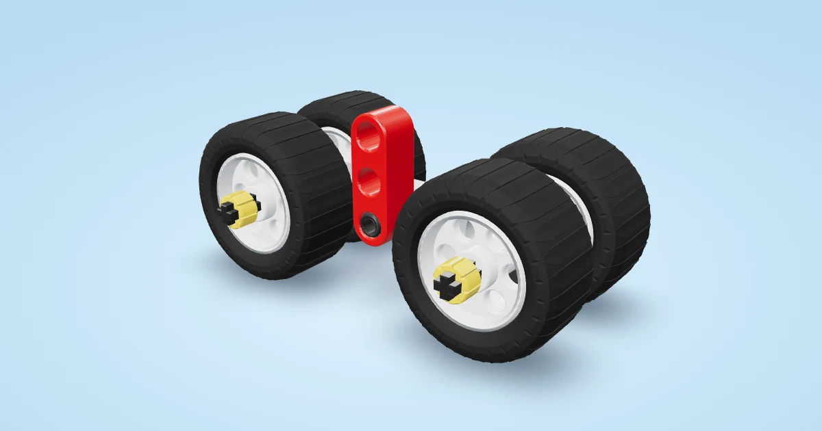 🚗 Tiny Roller: Your very first rolling car — only 13 pieces! (level 1 of 5, about 5 minutes, 6 steps)
Parts you need
- 1 × Open frame 5×7
- 4 × Blue long pin
- 4 × Split pin block
- 4 × Red axle-pin
- 2 × Beam 11
- 1 × Axle 12
- 4 × Half bush
- 1 × L-beam 3×5
- 2 × Black pin (grippy)
Steps
- Lay the 5×7 frame flat on a level table. Its two short ends will carry separate rigid posts.
- Insert two blue long pins upward through the second and fourth holes of the back short end. Fit two split pin blocks one above the other onto the same pins.
- Put a red axle pin in each back block’s centre cross hole, pointing backward. Two fixing points stop the post tipping.
- Stand an 11-hole beam at the back. Fit its second and third holes onto the back pair of red axle pins.
- Pass a 12-module axle through the back post’s ninth hole. Add a half bush against the outside of the back post. Slide another half bush to just behind the centre of the bench; it will meet the back face of the bent lever.
- Hang a yellow 3×5 L-beam on its corner round hole at the centre. The five-hole leg extends left and the three-hole leg points up. Add a half bush against its front face. The lever turns on the shaft; the bushes grip the shaft and retain the lever without squeezing it.
- Press a black friction pin into each outer end hole, pointing toward the front. They mark points four and two hole spacings from the pivot. The pins are markers, not payload hooks or extra bearings.
- Now add the front block pair: two blue long pins upward through the second and fourth holes, then two split pin blocks stacked on them. Adding these after the bent lever keeps its insertion path open.
- Fit two red axle pins pointing forward in the front blocks’ centre cross holes.
- Fit the front 11-hole post onto its two red axle pins while guiding the long axle through its ninth hole. The two posts are eight modules apart, supporting both ends of the pivot axle.
- Fit a half bush immediately outside the front post. Check both outside stops retain the whole axle, and the two centre stops retain the L-beam. Both posts need their two fixing pins. Leave the corner hinge free to turn.
Play time
Keep the frame on a level table and hold only the stationary frame. View the yellow lever from the front. Gently turn its long left arm downward by no more than 20° from the initial horizontal position; the short upper arm moves left. Return through the centre and try the opposite direction, staying within ±20°. Observe the end-marker centres against separate vertical and horizontal references, kept clear of the sweep. Both markers follow arcs, not straight guides. No physical angle stops, motor, rods, added weights or force rating are provided. Stop for loose markers, bushes, posts or rubbing. This unloaded educational model has not been physically tested.
Credited demonstrations and component sources
- Bell Crank Linkage — Bricks Master Builders: Independent bell-crank demonstration inspires the direction-change question. Our original single bent-lever bench has different supports, dimensions and instructions; it is not a reproduction of the complete linkage.
- OpenStax — Rotational Variables: Primary background for shared rigid-body angle and radius-dependent point travel. Our signed coordinate projections are an ideal geometry model, not physical measurements.